DKV-Conference
In-situ layout method for capillaries

This publication presents a novel in-situ method for designing and verifying the capillary and demonstrates its use in two practical examples.
Nomenclature
Abbreviations / Units
GF: (FC) Freezer compartment
KF: (RC) Refrigerator compartment
sl/min: Flow rate with nitrogen in standard liters* per minute through the capillary at an inlet pressure of 9.81 bar abs and free-blowing outlet. *Reference temperature 20 °C
Summary
In the refrigeration circuits of mass-produced products such as household refrigerators and air conditioning units, the capillary tube is usually the first choice as a throttling device. Until now, this decision has been accompanied by increased development costs, as the design of the capillary tube is not trivial. This is particularly the case if the connected system is to function reliably and efficiently over a wide operating range. During the development process, the system can be equipped with a replaceable capillary section, for example. In practice, however, the known methods have disadvantages such as significant changes in fill volume, difficult handling, long set-up times, or high infrastructure requirements.
This publication presents a novel in-situ method for designing and verifying the capillary and demonstrates its use in two practical examples. The first example applied the method to determine the effect of capillary tolerances on the operating behavior of a refrigerator. This is a test that would hardly be able to deliver reliable results without the approach presented. The second example illustrates the classic application of the equipment for specifying the throttle capillary in a small refrigeration circuit with flammable refrigerant. Thanks to the new method, the determination time was reduced by a factor of approximately 5.
1. Intro
Usually several meters long, with an inner diameter of less than one millimeter: as a throttling device, the capillary tube is a core component in the refrigeration circuit and just as important as the compressor. It boasts attractive properties: the tube is inexpensive, operates passively, is robust, and is easily reproducible. Due to its pressure drop, it simply adjusts the required evaporation temperature and refrigerant mass flow in the refrigeration cycle.
Modeling the physical processes in the capillary during refrigerant flow is highly complex. To date, it has not been possible to calculate the required or desired parameters for a capillary with satisfactory accuracy using a universally applicable correlation.
As soon as the refrigerant enters the capillary in liquid form, a pressure drop occurs in the direction of flow. This ultimately causes the refrigerant to pass into the two-phase dome. Gas bubbles form, which increase the flow velocity and lead to a further pressure drop, causing the formation of gas bubbles to increase further. This is a self-reinforcing process that only ends when the refrigerant exits the capillary.
When calculating these changes in state, one is confronted with topics such as the Fanno curve, supersonic flows, flow regimes, and their changes. The circulating oil is still completely disregarded in this calculation.
There are empirical and semi-empirical models that can be applied within certain limits, but become invalid when the boundary conditions change. If, in practice—and this is still the case in most instances—an internal heat exchanger is integrated, then even the best current model fails.
This is a highly unsatisfactory starting point for an efficient development process, as it relies on the experimental determination of capillary parameters in terms of length and inner diameter. The restrictiveness of the capillary depends heavily on the refrigerant charge. Even if subcooling is ensured, an additional charge generates a higher condensation pressure, resulting in an increase in mass flow and evaporation temperature.
Refrigeration circuits with a built-in capillary are usually very compact. In refrigerators, they are usually encased in foam in the insulating cavity between the interior and the outer casing. In addition, the fill quantity of such refrigeration circuits is very low. For a variety of reasons, it is not practical to determine the capillary iteratively by installing and removing different lengths and diameters.
– The consistent refrigerant charge is missing.
– Refrigerant circuit needs to be refilled (difficulty with refrigerant in the oil).
– Risk of blockages in the circuit.
– Risk of leaks in the refrigerant circuit.
– Accessibility is difficult or impossible.
It is also difficult when several devices are equipped with different capillaries.
– A high level of support requires a high-quality testing infrastructure.
– There are differences in the measurements due to different tolerances in the manufacturing process.
– Refrigeration circuit components
– Housing insulation
– Individual parts
– Control
– There are differences in the measurements due to tolerances in the sensors used.
A common aid in the development process is the integration of special throttle sections into the functional models. Such sections feature, for example, a distributor in the fluid line to which various capillaries are attached in the individual branches. There is a valve in each branch. Different capillaries can be activated or connected in parallel via the switch positions of the valves. This approach significantly increases the system fill volume. However, it is not possible to determine the fill volume using the functional model at the same time. Similarly, internal heat exchangers can only reproduce the thermal coupling of the capillary with another line to a limited extent.
The limitations in this regard result from the fact that each capillary branch would have to be connected to this line. Apart from the possible influence of the inactive branches on the active branch, such an implementation also poses a geometric problem.
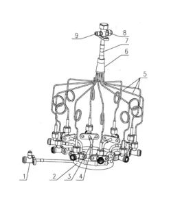
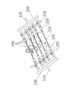
Figure 1: Examples of throttle sections with distributors (left: Xiande [1], right: An et al. [2])
The literature also describes a method involving segmented extension of the capillary length. In this method, capillary segments are connected in series using T-pieces and valves. Each T-piece causes pressure drops that do not correspond to the reality of a capillary tube: the refrigerant expands into a cavity, which then tapers again into the next capillary segment. Significant pressure drops occur at the latest when the speed of sound is reached. The segmented capillary is thus much more restrictive than a single-tube capillary with the same total length. With this approach, it is possible to form an internal heat exchanger.
Figure 2: Examples of segmental extensions of the capillary (left: Qiao et al. [3], right: Zhang [4])
2. The capillary tool
The in-situ layout method for capillaries is based on the integration of a special tool between the filter dryer (liquid line) and the evaporator inlet. This tool, referred to below as the “capillary tool,” makes it possible to select multiple capillary flows in a system with minimal impact on fill quantities and the option of integrating an internal heat exchanger.
The capillary tool consists of various parts. It comprises an inlet and an outlet segment (E and A), between which there is a mechanical construction consisting of a fixed part and a slider. A certain number of capillary segments (1..x) can be connected to the fixed part. The slider and the fixed part form flow channels inside, which connect the capillary segments in series. A selectable relative offset between the fixed part and the slider determines the number of capillary segments that are connected in series between E and A.
The capillary tool can be used to set x restriction levels (stages) for the throttle section. The characteristics of the x stages are determined by the design (lengths and inner diameters) of the individual segments. The capillary tool can therefore be configured for individual purposes.
Since the internal channels within the fixed part and slide are manufactured with an inner diameter that generally corresponds to the diameter of the connected capillary segments to within +/-0.05 mm, intermediate expansion is prevented. This means that the difference between the capillary tool and the final capillary and the impact on the system fill quantity is minimal.
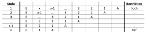
Table 1: Structure of the capillary tool
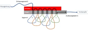
Figure 3: Illustration of the capillary tool at level 1
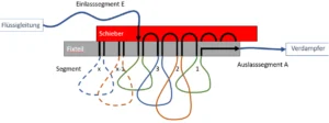
Figure 4: Illustration of the capillary tool at level 3
Assuming an exemplary configuration of the capillary tool with the segments according to Table 2, it can be seen how the capillary flow in situ can vary over 7 stages from 3.3 to 7.8 sl/min.

Table 2: Exemplary segment configuration for a wide range of variations
In this example, the tool would have different segment lengths on the fixed part and be able to cover a very wide flow range (Figure 5). The flow rate of 5.2 sl/min at stage 4 would correspond to the target flow rate calculated or specified by the developer, which can still be varied from -37 to +45%. Segment E is deliberately designed with a slightly larger inner diameter in order to achieve a practicable segment length for the implementation of an internal heat exchanger. The inner diameters of the segments may be reduced as they approach the evaporator. However, ideally they should not increase any further in order to minimize the risk of intermediate expansion.

Figure 5: Variation range of the capillary tool according to Table 2
The configuration shown in Table 2 is conceivable at a very early stage in the development process in order to narrow down the target capillary flow rate, which is practically unknown at that point. Despite the wide flow range, the difference in filling volume between the tool and the final capillary is very small. Assuming that the flow rate at level 4 (5.2 sl/min) is implemented with a capillary in the series product, this capillary would have a length of around 3.1 m with an inner diameter of 0.7 mm.
The internal volume of the capillary tool in the above configuration is approximately 3.9 cm³, while that of the final capillary is only 1.2 cm³. Calculating the fill volume in the capillary, including the internal heat exchanger, is complex. However, even a simplified calculation gives an idea of the still low influence of the fill volume when using the capillary tool. The most significant influence is the inlet section of the capillary, where the refrigerant is still in a liquid state. Assuming that 1/3 of the total volume is filled with liquid (density 0.5 g/cm³), this results in a difference of around 0.4 g.
The tool is configured using an in-house calculation program, which is used to theoretically define all segments. The flow rate for each stage is then measured on the manufactured capillary tool in a capillary test bench under the conditions specified by the customer. If necessary, the segments are readjusted so that the tool corresponds to the target characteristics. Currently, the ThermodynamX calculation tool predicts the flow rate per stage with deviations of +/- 5% from reality. The accuracy of the software can be improved by feeding back the measurement data.
3. Practical application of the capillary tool
3.1 Influence of supplier-side flow tolerance of capillaries on the system
Domestic refrigerators must meet the highest efficiency and market requirements. Regulations demand a gradual increase in efficiency, while customers are only willing to spend a limited amount of money on more efficient household appliances. In this area of conflict between quality- and manufacturing cost-conscious development and production, cumulative tolerances become a challenge. Efficiency is influenced by geometric tolerances of individual appliance parts and assemblies (e.g., gap dimensions), by the various component tolerances (e.g., compressor efficiencies), relative fill quantity tolerances (caused by the accuracy of the filling system), and volume tolerances of the refrigeration circuit components, to name just a few examples.
A Monte Carlo simulation showed that, among the various influencing factors, the capillary has a significant effect on the refrigerator’s energy consumption. In the underlying refrigerator model, the variation in the capillary was expressed via variable superheating for the calculation (Figure 6: Bless and Vetsch [5]).
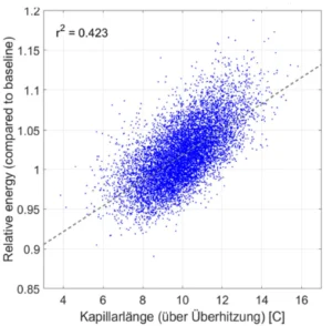
Figure 6: Influence of the capillary on energy absorption based on a Monte Carlo simulation
The capillary is supplied by the supplier with a flow tolerance of +/-5% as standard. With the methods mentioned in the introduction, it was not possible to measure the sole influence of this tolerance range on the efficiency of the refrigerator. It was neither possible to create a reliable data basis with which the additional costs of a tighter flow tolerance could have been justified, nor was it certain whether the current tolerance was sufficient for high manufacturing reliability.
A capillary tool was therefore configured in collaboration with V-ZUG Kühltechnik AG, which mapped the nominal flow rate and a range of approx. +/-5%. This was integrated into a single-circuit refrigerator (without capillary switchover valve) with a cooling compartment (KF) and an internal freezer compartment (GF). For simplicity’s sake, the appliance was equipped with a fixed-speed compressor. The refrigerant is injected into the GF evaporator via the capillary and then flows into the KF evaporator, which is connected in series. The KF temperature is regulated and the GF temperature is determined passively.
With regard to the capillary tool, it had to be taken into account that the filter dryer, at which the inlet segment starts, is located in the base of the refrigerator. Segment E is then laid along the suction line in a counterflow, thus creating an internal heat exchanger. The design consisting of a slide valve and fixed part with the 5 capillary segments is then installed in the upper part of the refrigerator, approx. 1.5 m above the floor. To ensure that there was sufficient physical length, E had to be designed with an inner diameter of 0.7 mm. The outlet section A then led to the injection point of the refrigerator under investigation.
The configuration shown in Table 3 allows the flow rate to be varied in increments of -5.2 to +6.5% of the nominal flow rate (level 3, 3.68 sl/min).
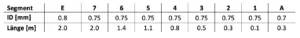
Table 3: Configuration of the capillary tool for the “manufacturing tolerance” use case
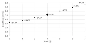
Figure 7: Measurement of the configuration according to Table 3
For various reasons, the final results of the study are not being presented in full. Firstly, the measurement and calculation practices used to determine the standard energy consumption of domestic refrigerators are currently undergoing a transition phase, with this initial test still being carried out in accordance with the “old standard.” Secondly, the details of the results and conclusions are protected know-how belonging to V-ZUG Kühltechnik AG.
However, the data from a cooling cycle show a measurable influence of the capillary flow tolerance on the average power consumption of the device under investigation (Figure 8). As the capillary flow decreases, the temperature in the freezer compartment also decreases as expected. The capillary lowers the temperature level at the evaporator, which is why more cooling capacity is required for the freezer compartment evaporator. The controller that monitors the freezer compartment temperature must therefore run the compressor for longer so that the same amount of energy can be extracted from the freezer compartment.
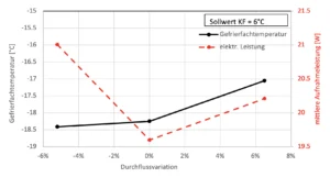
Figure 8: Influence of flow tolerance on the average power consumption of a cooling cycle (measurements at -3% and +3% still pending)
The fact that the electrical power consumption shows a minimum at 0% requires closer examination using Figures 9 and 10. As expected, the electrical power consumption of a fixed-speed compressor is higher when the capillary flow is greater. It is also clear to see how the compressor runs for longer at low flow rates in order to maintain the setpoint in the refrigerator compartment. The shorter running time at higher flow settings is far less obvious.
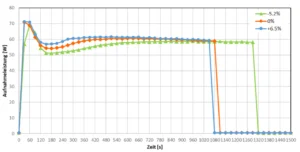
Figure 9: Power consumption curve at different flow rates with a target value of 6°C for the refrigerator compartment
Figure 10 below shows the inlet temperatures at the refrigerator compartment and freezer compartment evaporators, corresponding to Figure 9. At lower flow rates, the inlet temperature at the freezer compartment evaporator (GF_in) is lowest, but it takes the longest for the temperature at the refrigerator compartment evaporator (KF_in) to drop and for the refrigerator compartment to cool with a sufficient temperature difference. At the highest flow rate, KF_in does not drop significantly earlier than at the base level, which is why the running time differs only slightly. The reason for this behavior is probably due to a decrease in subcooling and must be investigated in further measurements. Nevertheless, it can be stated that this refrigeration circuit with a fixed-speed compressor reacts sensitively to tolerance fluctuations in the capillary flow with measurable effects in terms of energy efficiency. The extent to which a variable-speed compressor influences these effects remains the subject of future investigations.
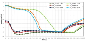
Figure 10: Temperature curves of freezer compartment and refrigerator compartment evaporator inlet at a setpoint of 6°C for the refrigerator compartment and various flow settings
3.2 Compliance with the operating range of a compressor
As part of the development of a new device with a cooling function, the cooling unit was implemented as a partially redundant dual unit. Both units are identical in design and equipped with a throttle capillary. R600a is used as the refrigerant. The cooling unit is designed to regulate the temperature of a self-contained room volume. The extracted heat energy is released into the environment via the condensers. A modulating electric heater regulates the interior temperature without temperature fluctuations. The cooling unit’s area of application involves two significant requirements.
a) At a room temperature of 25°C, it should be possible to cool the interior to 4°C. To do this, both units must be operated.
b) At a room temperature of 40°C, the interior should be heated to 37°C and the cooling system should operate at the highest possible evaporation temperature. Only one of the two units is operated.
The two variable-speed compressors should meet condition a) at maximum speed and one compressor should meet condition b) at minimum speed. Despite the passive capillary, the compressors should operate within their specifications.
The operating range is limited on the compressor side, especially under condition b). The condensation and evaporation temperatures must not exceed 60°C and 10°C, respectively, at minimum speed. Apart from the condenser, condenser fan, and fill quantity, the evaporation temperature is also determined by the restrictiveness of the capillary. In addition, the condensation temperature depends on the mass flow, which is limited by the capillary length. A restrictive capillary would keep the evaporation and condensation temperatures low and reduce the performance of the system at all operating points.
Condition a) is therefore decisive for determining the capillary when the compressors are operating at maximum speed. The capillary must be sufficiently “large” so that the cooling capacity required to achieve the setpoint is available. However, the evaporation temperature must also be kept ≤ -5°C under this aspect.
Two capillary tools were used when commissioning the double unit. This allowed the capillary to be varied on both units in 10 flow stages over a range of approximately 4–6 sl/min. It also enabled the simultaneous creation of an internal heat exchanger with segment E. Thanks to the use of the capillary tools, no changes to the refrigeration circuits were necessary to determine the capillary lengths and fill quantities, and various fill quantity/capillary combinations could be tested in a short time.
Stage 7 with 5.2 sl/min meets the system performance requirements. At an ambient temperature of 25°C, it achieves 4°C in the interior with power reserve. This occurs at an evaporation temperature of -7°C.
At an ambient temperature of 40°C and an interior temperature of 37°C, the refrigeration circuit operates at an evaporation temperature of 7°C and a condensation temperature of 59°C. Both requirements are met with a slight margin, so that certain flow and fill volume tolerances can be accommodated in series production. An average of five different flow rates could be tested within one day. With a conventional approach involving replacement of the capillary, it would have been possible to test approximately one variant per day.
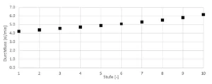
Figure 11: Measurement of the configured capillary tool for the “working range” application
4. Summary
The capillary tool opens up new possibilities for an efficient development process for refrigeration circuits with a wide operating range and a capillary as a throttling device. It can also be used for various experimental investigations and analyses. The tool has a compact design. It can be integrated even in small installation spaces and has only a very minor effect on the filling quantity of the refrigeration circuit (approx. 0.5 g). The flow specification determined with the capillary tool can be transferred 1:1 to the production of a capillary tube.
The capillary tool consists of a fixed part and a slider, in which an inlet and outlet segment as well as x step segments of capillaries are inserted. Depending on the relative offset between the fixed part and the slider, a sequential interconnection of the inlet segment, step segments, and outlet segment is created. This results in a flow value for each switch position. The capillary tool is configured by selecting the segment lengths and inner diameters and the number of step segments.
The use of the capillary tool in a refrigerator demonstrated the effect of the manufacturer’s tolerance for capillaries on the operating behavior of the appliance. Starting from the baseline (0%) with control set to a KF setpoint of 6°C, at a flow rate of 5.2%, the GF temperature drops by 0.1 K and the power consumption increases by 7%. At a flow rate of +6.5%, the GF temperature rises by 1.2 K and the power consumption increases by 3%.
The tool proved to be very helpful in another project to meet two conflicting requirements for a refrigeration circuit with capillaries. The “maximum cooling capacity” requirement calls for a less restrictive capillary, while the maximum condensation and evaporation temperatures permitted by the compressor require a certain limitation of the flow rate. It was possible to vary the capillaries in 10 steps and thus test different fill quantities/capillary ratios without any modifications to the refrigeration circuit. With this approach, the test time for capillary definition was estimated to be a factor of 5 shorter than with an iterative approach (with modifications).
Literatur
[1] Xiande, L. (2010) Apparatus of air conditioner for matching capillary tubes (CN201666699U). https://worldwide.espacenet.com/patent/search/family/043267658/publication/CN201666699U?q=pn%3DCN201666699U
[2] An, J., Liang, G., Shi, Z., Wang, Q., Wie, S., Zhou, J. (2014) Capillary matching device (CN203785344U). https://worldwide.espacenet.com/patent/search/family/051321522/publication/CN203785344U?q=CN203785344U
[3] Qiao, G., Wang, R., Wang, Y., Zhang, Z. (2019) Tool for determining target capillary tube (CN110160288A). https://worldwide.espacenet.com/patent/search/family/067640161/publication/CN110160288A?q=CN110160288A
[4] Zhang, W. (2017) Dynamic length regulation device for refrigeration capillary tubes (CN107388645A). https://worldwide.espacenet.com/patent/search/family/060354154/publication/CN107388645A?q=CN107388645A
[5] Bless, F., Vetsch, B. (2017) MonteCarlo-Simulation – Wirkung der statistischen Streuung von Einzelparametern auf die Gesamteffizienz eines Kühlschranks. Interner Bericht für die V-ZUG Kühltechnik AG.
Cool solutions for hot results.
We always step in when thermally complex, sustainable, and market-ready solutions are needed..
